The advantages of high brightness, low power consumption, miniaturization and long life have led to the rapid development of this technology, but LED lighting technology still has the challenges of high cost, large heat sink, low luminous efficiency and dimming. During the design process, engineers often encounter slow start-up, flicker, and uneven illumination when performing LED conventional adjustments. Therefore, how to solve the problem of LED flicker has become an urgent task for engineers. If high-precision constant-current control can be provided (can analyze the variable phase angle output of the thyristor controller and unidirectionally adjust the constant current flowing to the LED), the input EMI filter has very small inductance and capacitance, then it is effective. Can flashing dimming be possible? Power Integrations (PI)'s LinkSwitch-PH series of LED driver ICs have solved this problem well. The primary side control technology of the product also eliminates the optocouplers and auxiliary circuits commonly used in isolated flyback power supplies (ie The secondary side control circuit), while the PFC part of the controller also eliminates the large-capacity electrolytic capacitor, which brings a great boon to the LED flicker-free dimming. Incandescent lamps can be easily dimmed using a simple, low-cost, leading-edge TRIAC dimmer. Therefore, this dimmer can be seen everywhere. Solid-state lighting replacement lamps must be able to use existing controllers and lines for dimming in order to be truly successful. Incandescent bulbs are ideal for dimming. The irony is that their inefficiency and the resulting high input current are the main factors that make the dimmer work well. The thermal inertia of the filament in an incandescent bulb also helps to mask any instability or oscillations produced by the dimmer. A number of problems have been encountered in trying to dim LED lights, often resulting in flicker and other unexpected situations. To understand why, it is first necessary to understand how thyristor dimmers work, LED lamp technology, and the interrelationships between them. Figure 1 shows a typical leading edge TRIAC dimmer and the voltage and current waveforms it produces. Potentiometer R2 adjusts the phase angle of the thyristor (TRIAC). When VC2 exceeds the breakdown voltage of DIAC, the thyristor turns on at the leading edge of each AC voltage. When the thyristor current drops below its holding current (IH), the thyristor turns off and must wait until C2 is recharged in the next half cycle before turning it back on. The voltage and current in the filament of the bulb are closely related to the phase angle of the dimming signal, and the phase angle varies from 0 degrees (nearly 0 degrees) to 180 degrees. LED lamps used to replace standard incandescent lamps typically contain an array of LEDs to ensure uniform illumination. These LEDs are connected together in series. The brightness of each LED is determined by its current. The forward voltage drop of the LED is approximately 3.4 V, typically between 2.8 V and 4.2 V. The LED string should be driven by a constant current source and the current must be tightly controlled to ensure a high degree of matching between adjacent LEDs. In order to achieve dimming, the LED lamp must be able to analyze the variable phase angle output of the thyristor controller in order to unidirectionally adjust the constant current flowing to the LED. It is very difficult to do this while maintaining the dimmer's normal operation, often resulting in poor performance. The problem can be manifested as slow start-up, flicker, uneven illumination, or flicker when adjusting the brightness. In addition, there are problems such as inconsistencies between components and unwanted audio noise emitted by LED lamps. These negative conditions are usually caused by false triggering or premature shutdown of the thyristor and improper control of the LED current. The root cause of false triggering is current oscillations when the thyristor is turned on. Figure 2 illustrates this effect graphically.
Today, LED lighting has become a mainstream technology. LED flashlights, traffic lights and lights are everywhere, and countries are pushing to replace incandescent and fluorescent lights in residential, commercial and industrial applications powered by mains with LED lights. After switching to energy-efficient LED lighting, the energy savings achieved will be amazing. In China alone, according to government estimates, if one-third of the lighting market turns to LED products, they will save 100 million kWh of electricity per year and reduce CO2 emissions by 29 million tons. However, there is still a problem to be overcome, that is, the dimming problem.

Figure 1. Front edge thyristor dimmer
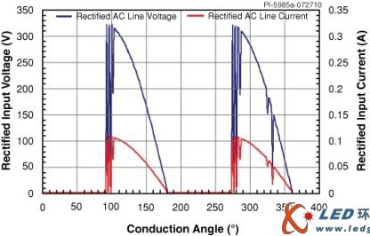
Figure 2. SCR current and voltage oscillations occurring at the input stage of the LED lamp power supply