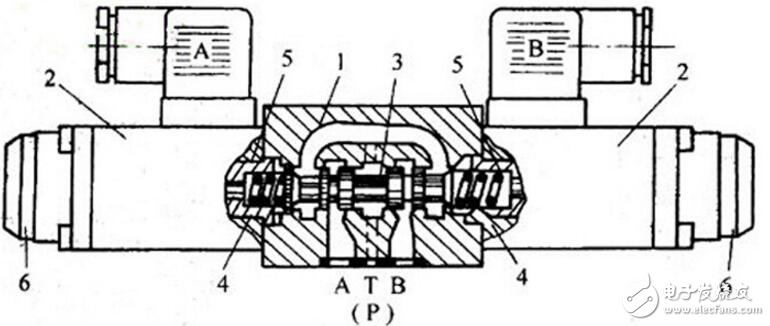
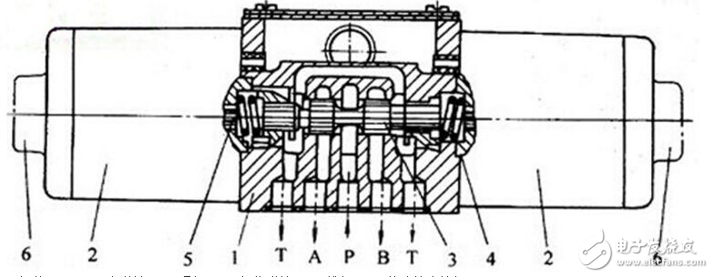
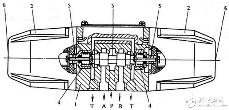
The basic working principle of the electromagnetic reversing valve is the same. The different positions of the spool of the spool valve are controlled by an electromagnet to change the flow direction of the shaped oil. When the electromagnet is de-energized, the spool valve is held in the middle or initial position by the spring (except for the impulse valve). If the fault check button is pushed, the spool of the spool valve can move. The next four figures: Figure 1, Figure 2, Figure 3 and Figure 4 are the structural principle diagrams of the WE type electromagnetic directional valve with different diameters. Figure 1 The schematic diagram of the structure of the WE5 solenoid directional valve 1—Valve body; 2—Electromagnet (AC electromagnet on the left. DC electromagnet on the right) 3—Spool valve; 4—Reset spring; 5—Push rod; 6—Failure check button 7—Rubber protective cover Figure 2 Schematic diagram of the structure of the WE6 solenoid directional valve 1—Valve body; 2—Electromagnet; 3—Spool valve; 4—return spring; 5—push rod; 6—fault check button Figure 3 Schematic diagram of the structure of the 4WE10E10/A wet solenoid directional valve 1—Valve body; 2—Wet display electromagnet; 3—Slide valve; 4—return spring; 5—push rod; 6—fault check button Figure 4 The structure principle diagram of 4WE10E10/L... dry AC solenoid directional valve 1—valve body; 2—dry electromagnet; 3—spool valve; 4—return spring; 5—push rod; 6—fault check button Fiber optic adapter are used in fiber optic connection, the typical use is to provide a cable to cable fiber connection. People sometimes also name them to be mating sleeves and hybrid adaptors, mating sleeves means this fiber optic adapter is used to connect the same type fiber optic connectors, while hybrid adaptors are the fiber optic adaptor types used to connect different kinds of fiber optic connectors. YLTelecom`s fiber adapter provide reliable solution for fiber connections, single mode fiber optic adaptors and multimode fiber optic adaptors available on request. We adopt high quality raw materials and make these fiber optic adapters strictly according to international standard, this makes our fiber optic adaptors with high performance.
Fiber optic adapters (also called couplers) are designed to connect two fiber optic cables together. They come in versions to connect single fibers together (simplex), two fibers together (duplex), or sometimes four fibers together (quad).
When connecting two multimode fibers, you should always make sure they are the same core diameter (50/125 or 62.5/125). A mismatch here will cause attenuation in one direction (where the larger fiber is transmitting light into the smaller fiber).
Fiber optic adapters are typically connecting cables with similiar connectors (SC to SC, LC to LC, etc.). Some adapters, called "hybrid", accept different types of connectors (ST to SC, LC to SC, etc.). When the connectors have differing ferrule sizes (1.25mm to 2.5mm), as found in LC to SC adapters, the adapters are significantly more expensive because of a more complicated design/manufacturing process.
Fiber Optic Adapter, Fiber Optic Cable Adapter, SC Fiber Optic Adapter, ST Fiber Optic Adapter, FC Fiber Optic Adapter NINGBO YULIANG TELECOM MUNICATIONS EQUIPMENT CO.,LTD. , https://www.yltelecom.com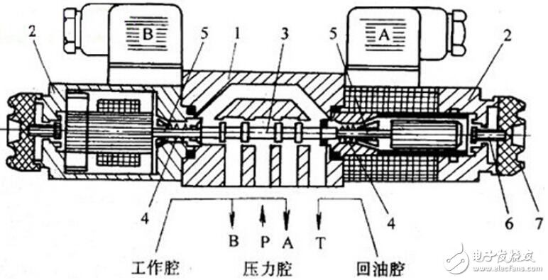
Fiber Optic Adapters FC, SC, ST, LC, MT-RJ, MU, E2000, FC/APC, SC/APC, LC/APC, E2000/APC, Simplex, Duplex, Quad, mating sleeves, hybrid fiber optic adapters, Single mode fiber optic adapters, multimode fiber optic adapters are all available.
Adapters are designed for multimode or singlemode cables. The singlemode adapters offer more precise alignment of the tips of the connectors (ferrules). It is ok to use singlemode adapters to connect multimode cables, but you should not use multimode adapters to connect singlemode cables. This can cause misalignment of the small singlemode fibers and loss of signal strength (attenuation).

Electromagnetic reversing valve structure diagram
var videoObject = {container:'.video', variable:'player', autoplay: true, html5m3u8: true, video: "https://vdse.bdstatic.com//dcc4a31878734a3fb39c16fd32177b5e?authorization=bce-auth-v1%2F40f207e6485424f10b2e %2F2017-05-11T09%3A02%3A31Z%2F-1%2F%2F97da6828c5dc6497eb4001710209beb4add92131d1c7a07753d42b80e2394fca" }; if (!! window.ActiveXObject) {videoObject.html5m3u8 = false} varvideo player = new directional valve structure; principle