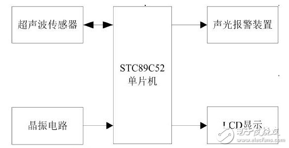
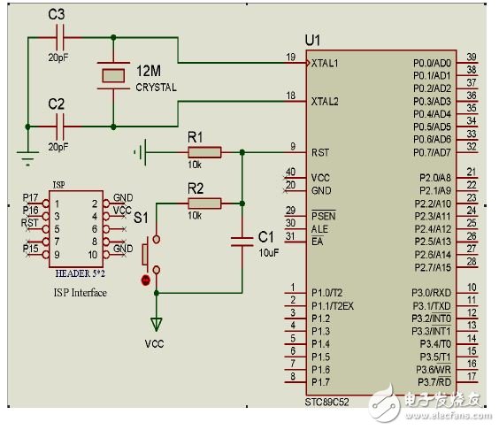
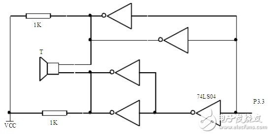
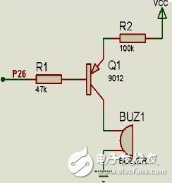
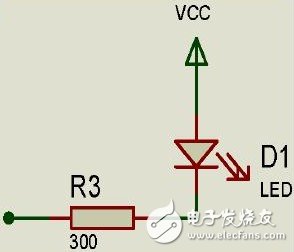
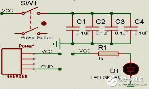
1 Basic principle of sound and light alarm system Ultrasound refers to mechanical waves with a frequency higher than 20,000 Hz. In order to achieve ultrasonic echo ranging, ultrasonic waves must be generated and received by ultrasonic sensors. Ultrasonic sensor uses the principle of piezoelectric effect and inverse piezoelectric effect to realize the mutual conversion between electric energy and ultrasonic energy. That is, the ultrasonic transmitter converts electric energy into ultrasonic energy through inverse piezoelectric effect, and generates ultrasonic waves; and the ultrasonic receiver passes through The piezoelectric effect converts ultrasonic energy into electrical energy and receives ultrasonic waves. If the ultrasonic wave emitted by the ultrasonic transmitter propagates in the medium at the speed v (unit: m/s), the ultrasonic wave of the measured object is reflected in the effective protection area, and is received by the ultrasonic receiver, and the propagation time is t ( Unit: s), then the distance s (unit: m) between the intruder and the guard object can be calculated. The formula is: The system block diagram is shown in Figure 1. The MCU receives the intruder distance electrical signal from the ultrasonic sensor output according to the clock timing given by the crystal oscillator circuit, and displays the distance value in real time on the LCD display. An audible and visual alarm system consisting of a tube and a buzzer that flashes at a certain frequency and sounds an alarm. Figure 1 System block diagram 2 system hardware design 2.1 hardware circuit The design of the hardware circuit mainly includes the single-chip system and display circuit, the ultrasonic transmitting and receiving circuit, and the sound and light alarm circuit. The single-chip microcomputer adopts STC89C52. It adopts 12 MHz high-accuracy crystal oscillator to reduce measurement error. The ultrasonic sensor uses a piezoelectric ultrasonic transducer, which sets the 40 kHz square wave signal required for the ultrasonic transducer to be output from the single-chip port P2.7, and the port P3.2 monitors the return signal output from the ultrasonic receiving circuit. The display circuit uses the KXM12864M display. The sound and light alarm circuit is composed of a light emitting diode and a buzzer. 2.2 Hardware of each major module 2.2.1 STC89C52 main control circuit Figure 2 STC89C52 main control circuit 2.2.2 Ultrasonic Transmitting and Receiving Circuit Piezoelectric ultrasonic transducer realizes the conversion between ultrasonic energy and electric energy through the resonance of piezoelectric crystal, thereby realizing the transmission and reception of ultrasonic waves. The ultrasonic transmitter is installed at the J1 end, and the square wave electric signal is outputted by the P27 port of the single chip at a frequency of 40 kHz. Then, the piezoelectric crystal undergoes an inverse piezoelectric effect to vibrate at the same frequency, thereby realizing the conversion of the electric energy to the ultrasonic energy. Ultrasound, as shown in Figure 3. Figure 3 Ultrasonic Transmitting Circuit The ultrasonic receiving device is installed at the J2 end. When no electric signal is applied to both ends of the piezoelectric crystal, when the ultrasonic signal is received, the piezoelectric crystal will have a piezoelectric effect and vibrate at the same frequency to realize the conversion of the ultrasonic energy to the electric energy. The electrical signal, which is amplified by the LM358 and sent to the LM567 for phase-locked loop detection, then the microcontroller can detect a local wave. As shown in Figure 4 below. Figure 4 ultrasonic receiving circuit 2.2.3 Display circuit The display circuit uses the KXM12864M LCD display. 2.2.4 Sound and light alarm circuit As shown in Figure 5, the acoustic alarm circuit uses a piezoelectric buzzer. When the MCU outputs a low level, the triode is turned on and the buzzer alarms. Figure 5 acoustic alarm circuit As shown in Figure 6, the optical alarm circuit, when the microcontroller outputs a low level at the corresponding port, the green, yellow and red LEDs flash at different frequencies. Figure 6 light alarm circuit 2.2.5 Power circuit As shown in Figure 7, the power supply VCC consists of 2 to 4 5th battery packs. C1, C2, C3, and C4 act as voltage regulators. When the switch SW1 is pressed, the green LED emits light. Figure 7 power circuit 48V 100AH Powerwall Solar Battery Shenzhen Jiesai Electric Co.,Ltd , https://www.gootuenergy.com