In the first part, we introduced the different LED lighting technologies used in capacitive sensing UI applications through practical use cases. Below we will look at the different ways to implement pulse width modulation ( PWM , a key technology for LED control applications). PWM has two major properties: Frequency: Use the PWM signal to quickly switch the LED. Since the switching frequency will produce LED flashing, the PWM frequency should be greater than 100 Hz to ensure that the human eye does not feel flicker. Duty Cycle: The PWM controls the brightness of the LED by changing the duty cycle and keeping the load current constant. The average current of the LED depends on the duty cycle. The average current rises as the duty cycle increases, which in turn increases brightness. The number of steps between 0% and 100% duty cycle should meet the different brightness level requirements that need to be adjusted in the application. For example, if the application requires 20 brightness levels between fully off (0%) and fully on (100%), then 5% of the step size should be supported (20 steps in addition to full shutdown). There are two ways to implement PWM with a microcontroller. We can implement the entire PWM logic in firmware with a simple timer/counter, or we can choose an advanced controller that integrates hardware PWM functions. Firmware-based PWM implementation A simple firmware implementation requires a timer and an interrupt service routine (ISR). The timer creates an interrupt for the same amount of time as each step of the duty cycle. For example, if the PWM period is 10ms (100Hz) and the step size is 1ms (10% duty cycle), then the timer will interrupt the CPU every 1ms, ie: timer period = pulse width / step size size. Figure 1 shows the logic in the ISR. PULSE_WIDTH and ON_TIME represent the pulse width and turn-on time of the number of PWM steps. For example, PULSE_WIDTH = 5 satisfies the requirements of 5 brightness levels, while ON_TIME = 2 satisfies the 40% duty cycle requirement. The ISR variable isrVar controls when the output toggles on/off. This logic can be easily extended to support multiple LED pins, each with a different duty cycle. Hardware-based PWM implementation The advanced controller has dedicated hardware blocks that drive the PWM. For example, Cypress's PSoC4 has a TCPWM hardware block that enables hardware-based PWM drivers. In general, we implement it with a timer with a compare function, similar to the firmware logic discussed above. The timer will use the compare register and the period register. The value loaded by the period register is equal to the pulse width, and the value loaded by the compare register is equal to the on time. As long as the comparison value is greater than the tick value, the timer output will go higher, and vice versa. In addition, when the tick value reaches the maximum (16-bit timer is 65535), it will automatically roll back to zero. When the output is routed to the port pins, the LEDs can be driven directly by the hardware block. Table 1 summarizes the differences between firmware-based and hardware-based PWM implementations. We analyzed different ways to implement PWM in this section. In the third part, we will explore the common challenges and solutions for designing systems with capacitive sensing and LED lighting.
MARSHINE JC1000 route measuring meter weighs 3kg, and its order number is 21581. This product possesses single wheel. It can be suited for both indoor and outdoor distance measurement with the maximum measuring distance of up to 9999.9m.
Ningbo MARSHINE Power Technology Co., Ltd. is a professional engaged in the development, design and manufacture of power engineering construction equipment and tools.
Route Measuring Meter,Cable Length Measuring Meter,Digital Distance Measuring Wheels,Folded Distance Length Roller MARSHINE , https://www.puller-tensioner.com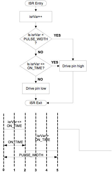
Figure 1: Firmware PWM ISR Logic 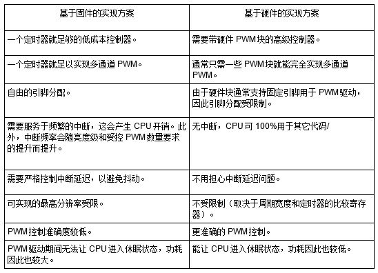
Table 1: Firmware-based and hardware-based PWM implementations
Route Measuring Meter
MARSHINE company produces circuit construction tools, including foundation construction, tower group lap. Wiring structure. Cable construction, cable construction, mobile knife mill, insulated overhead cable and high voltage cable stripper, all kinds of aluminum alloy pull rod, guide rail, grounding device, high strength shackle, ratchet wrench and pointed wrench, double hook tight line device, lifting pulley, nylon wheel and aluminum wheel, punching machine ect.
MARSHINE continues to carry forward the enterprise spirit of "integrity, development, innovation" and strive for the prosperity and development of the electric power industry.
Welcome to contact MARSHINE and reach cooperation, thank you!
Design of capacitive sensing combined with LED lighting (2)
0 times
Window._bd_share_config = { "common": { "bdSnsKey": {}, "bdText": "", "bdMini": "2", "bdMiniList": false, "bdPic": "", "bdStyle": " 0", "bdSize": "24" }, "share": {}, "image": { "viewList": ["qzone", "tsina", "tqq", "renren", "weixin"], "viewText": "Share to:", "viewSize": "16" }, "selectShare": { "bdContainerClass": null, "bdSelectMiniList": ["qzone", "tsina", "tqq", "renren" , "weixin"] } }; with (document) 0[(getElementsByTagName('head')[0] || body).appendChild(createElement('script')).src = 'http://bdimg.share. Baidu.com/static/api/js/share.js?v=89860593.js?cdnversion=' + ~(-new Date() / 36e5)];