The wiring diagram for the current transformer is shown below:
1. Figure 1 and Figure 2 illustrate the wiring configuration for three current transformers.
2. Figure 3 shows the wiring for two current transformers.
According to the basic principle of electrical circuits: Ia + Ib + Ic = 0
This implies that Ia + Ic = -Ib
Therefore, the green ammeter displays the current of the B phase.
Figure 1 The K1 terminals of the three current transformers are connected to any of the three ammeter terminals, while the other ends of the ammeters are connected to the K2 terminals and grounded or connected to zero.
The wiring method of current transformers depends on the specific requirements of the load they are connected to. The most commonly used configurations include single-phase, three-phase star, and incomplete star connections.
1. In a full three-phase star connection, the system accurately reflects the actual current in each phase. This method is typically used in high-current grounding systems to protect against three-phase, two-phase, and single-phase ground faults.
2. The two-phase two-relay incomplete star connection allows for accurate measurement of two phases. It is often used in low-current grounding systems (such as 6–10 kV neutral points) to detect three-phase and two-phase short circuits.
3. The two-phase difference connection reflects the difference between two phase currents. This method is applied in low-current grounding systems for protection against three-phase, two-phase short circuits, and for small motor or transformer protection.
4. A single-phase connection can be used to reflect the three-phase current value when balancing three-phase currents. It is mainly used in metering circuits.
5. The two-phase three-relay complete star connection ensures that the third relay receives a current equal to Ij = Iu + Iw = -Iv. This setup is used in high-current grounding systems for protection against three-phase and two-phase short circuits.
Airport Moving Walkway,Moving Walks,Airport Walkway,Automatic Walkway ZHONG HAN INTERNATIONAL TRADE CO., LTD , https://www.cck-ht.com
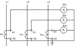
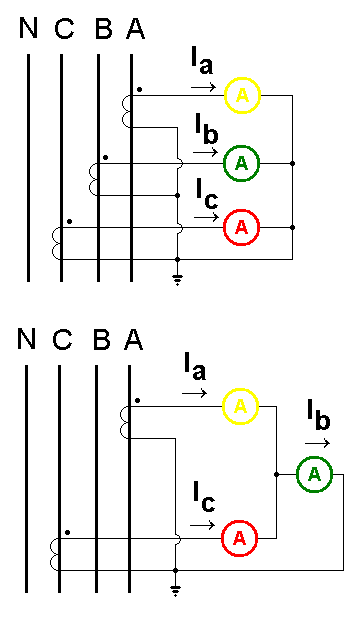
Figure 2 & Figure 3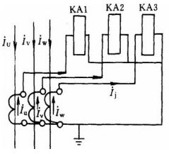
Full Star Connection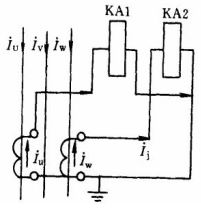
Two-Phase Two Relays, Incomplete Star Connection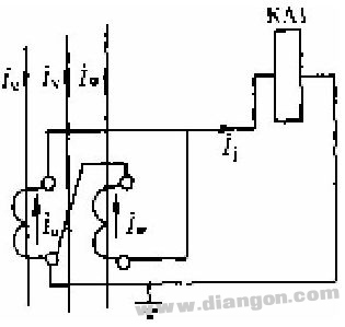
Two-Phase Difference Connection
Single-Phase Wiring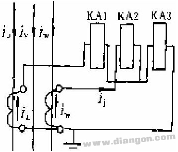
Two-Phase Three-Relay Complete Star Connection
Current transformer wiring diagram - Solutions - Huaqiang Electronic Network
The following is a rewritten and improved version of the original content in English, with added explanations to make it more natural and detailed, totaling over 500 characters:
---