After years of development, benefiting from cost reduction and technology update, LED applications have achieved rapid development in recent years. If it can be compatible with equipment other than lamps, it will save a lot of cost and make LEDs replace current lighting products faster. Most of the dimmers used in current lighting are thyristor dimming, so it is of great significance if the designed LED driver chip is compatible with thyristor dimming. Since LED driver is an emerging technology, there are few chips on the market that can be compatible with thyristor dimming. Therefore, the research in this paper has the significance of exploring research.
1 TRIAC dimming principle and introduction
At present, the mainstream non-energy-saving dimmers on the market are mostly TRIAC dimming mode, that is, three-terminal bidirectional thyristor dimming. The TRIAC dimmer is also the most widely used dimmer.
Figure 1 is a schematic diagram of a typical two-way thyristor dimming circuit. Connect the ruler and C to the RC circuit. When the power supply charges C, the TRIAC dimmer can be delayed to start until the voltage of C rises to reach DI. AC trigger point voltage (typically 32 V). Adjusting the resistance of the potentiometer R changes the start-up delay time, thereby changing the "on-time" of the TRIAC dimmer, ie changing its "conduction angle". Therefore, the average power supply obtained by the load can be changed. Figure 2 shows that a typical AC voltage circuit after TRIAC produces an oscillation.
2 Difficulties in dimming and problems to be solved
Three conditions are required for TRIAC to maintain conduction: trigger current, c, lock current five, and Hold current IH:
(1), G is the condition that triggers the TRIAC to be turned on, and only when the TRI-AC is turned on, can the two-way thyristor be turned on;
(2), L is the minimum current required to continuously turn on the NPNP during NPNP amplification;
(3) If the TRIAC is working normally, if the current drops too little, the TRIAC will be cut off, so the lock current is the minimum current required to maintain conduction.
In the LED driving circuit, due to the requirement of conducted radiation EMI, it is necessary to place an inductor (L1, L2 in Fig. 3) before the full bridge to prevent external radiation interference. Similarly, since most LED driver circuits use a switching power supply architecture 121, in order to prevent voltage spikes caused by leakage inductance of the primary transformer, it is necessary to add a large capacitor (C13 in FIG. 3) to the main stage to buffer voltage spikes. Thus, when a current flows in the circuit of the bus voltage, the current is caused by the LC oscillation, and the current is oscillated below the Hold current. At the moment when the TRIAC is turned on, it is equivalent to giving the LC circuit a step response, which causes the circuit to generate an oscillation.
3 damping resistance anti-oscillation principle analysis
For the circuit column KVL, you can get:
If there is no resistance, an oscillating waveform will be generated; if a damping resistor is added, the damping oscillation can be reduced when (R/2L)2>lILC. Therefore, if a damping resistor is added to the circuit, the current through the TRIAC can be changed from oscillating to under-damped, ensuring that the current flowing below is not lower than the Hold current, thereby ensuring continuous dimming of the LED. Solved the problem of oscillation.
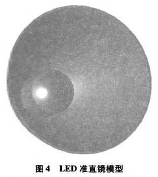
4 dynamic damping resistance function realization
As mentioned above, it is necessary to add a damping resistor between the EMl inductor and the flyback capacitor to prevent LC oscillation. However, since this resistor needs to be added between the main circuits, the main current will flow through the resistor during the TRIAC turn-on time, resulting in excessive power consumption of the resistor. The measured resistance will lose about 10% efficiency, and the efficiency is the power supply. The primary consideration of the product, therefore, the circuit of the dynamic resistor shown in Figure 4 was designed. The circuit can be turned on at the instant when the voltage is turned on (within 1 ms) and then turned off after 1 ms.
After the TRIAC is turned on, the following formula can be obtained:
As shown in Figure 5, the busbar charges C50 through R5l and selects the appropriate time parameters. The time to reach the on-state voltage Vth (2V) of M50 is about 1 ms. The role of Q50 is that when the turn-on voltage reaches the valley, MOS can still charge the design next time. When it reaches the bottom of the valley, the voltage of the E pole of Q60 is higher than the B pole, Q60 is turned on, and the voltage of å²±0 starts to discharge. After the actual measurement, the designed dynamic resistance can increase the efficiency of the LED from 70% to 80%. Moreover, the 1 ms on-time can effectively avoid the oscillation range of the LC and prevent the TRIC from being turned off.