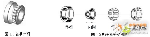
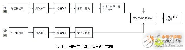
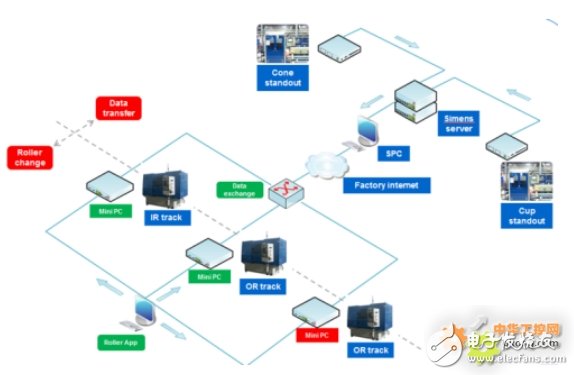
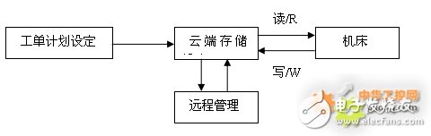
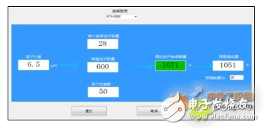
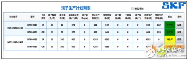
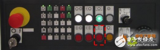
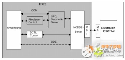
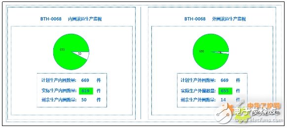
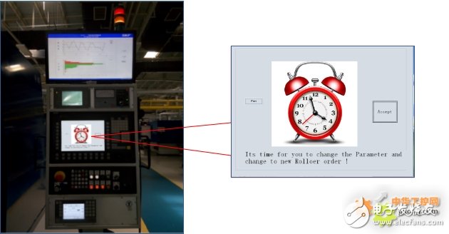
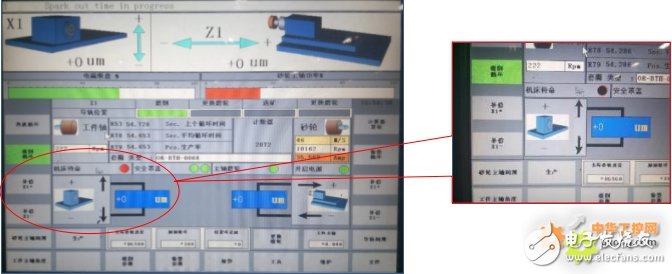
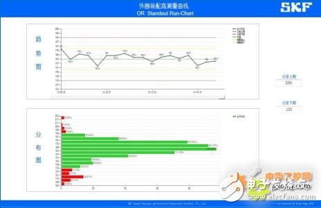
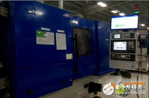
Summary: This system is developed based on the CNC Dynamic Data Exchange (NC DDE) supported by the Siemens 840D SL CNC system. The system is applied to the entire production line of the bearing production line from front-end grinding to post-assembly, and the program is automatically turned on and run in the background, real-time Collect monitoring data, and interact with the work order set by the remote cloud. After the product quantity reaches the predetermined quantity, the machine tool will be automatically controlled to stop running. After confirmation, the next work order plan will be automatically started, which solves the problem of bearing rolling. Sub-tolerance range is too large for the assembly problem; at the same time, the system integrates a mathematical statistical process control system to realize real-time dynamic analysis of the assembly tolerance range of the production assembly area, and automatically control the machine tool, realize the automatic grinding parameter compensation of the machine tool, and realize the production automation and Intelligent, greatly improving product quality. SKF, as one of the world’s largest bearing manufacturers, established SKF (Jinan) Bearings and Precision Technology Products Co., Ltd. in Jinan in 2011. The Jinan plant is an important part of the SKF Group’s automotive business unit in 2012. Since it was put into production, it has mainly served the auto parts market and industrial market in China and Asia. At present, it mainly produces tapered roller bearings TRB and double row cylindrical roller bearings (THU). SKF Bearings, which is known for its high product quality, has been controlling production with high-quality and high-standard requirements during the manufacturing process. However, in the initial stage, due to factors such as long production lines and delayed employee response time, it is inevitable that it will There is a problem of low assembly qualification rate of the whole product. Based on this background, we have carried out related transformations to the key equipment of the Siemens 840D CNC system, and developed this system based on the actual situation on the site, which solved the related problems. The response is lagging, which improves the product qualification rate, and the increased production benefit is very considerable. 1.1 Introduction to the production process The basic processing flow of the bearing is: the inner ring and outer ring of the bearing are automatically ground at the corresponding grinding station according to the layout of the production line, and they are respectively subjected to cylindrical grinding, end surface grinding, raceway grinding, inner hole grinding, After the ribs are ground, they enter the inspection and assembly area for inspection and assembly combination. 1.2 Introduction to production line equipment Since 2012, the company has successively introduced foreign precision grinding processing equipment and domestic bearing testing and assembly equipment. All grinding equipment adopts Siemens 840Dsl control system, and adopts the powertrain standard of the automobile industry. The main configuration of the numerical control system is as follows: NCU 710.2, PCU50.3 (loaded with HMI Advanced, based on Windows XP, dual network cards), MPP483 IE and Corresponding to servo drives and motors, etc. The equipment meets the requirements of automation in terms of electrical control and mechanical accuracy, and mainly realizes the precision grinding of bearing inner and outer ring blanks: external cylindrical grinding, raceway grinding, inner hole grinding and other technological processes. The assembly equipment mainly uses Siemens S7-200 PLC as the controller, equipped with corresponding mechanical, electrical and pneumatic structures, and mainly realizes the cleaning, inspection, assembly, riveting, and grease injection of the bearing inner ring, roller, cage and bearing outer ring Wait for the later process. 1.3 Problem description In the production process, the grinding process deviation at the front end of the production line, the tolerance of the roller, the height of the inner component, the height of the outer ring, etc. will directly affect the final assembly pass rate. Therefore, the following problems currently exist: Question 1. Roller batch tolerances are different. Different batches of rollers have different roller tolerances. According to the theory, the same number of rollers should be used to produce corresponding bearings. For example, there are 20 rollers in the BTH-0801 model bearing, and the batch of rollers is T, so the theory produces bearings. The quantity is N=T/20, that is, the inner and outer rings need to be theoretically produced N. However, in the actual process, because the production line is too long, the quantity stranded on the conveyor belt and due to scrap, rework, etc. cannot be effectively and accurately measured, which causes a large deviation and has a large impact on the production quality. Question 2. The grinding compensation response is delayed. Due to the influence of grinding stability and roller tolerances, corresponding deviation trends will occur. For example, the process deviation is too high or too high. The corresponding inner and outer ring grinding raceway grinding process requires manual compensation control to improve the assembly qualification rate. However, due to the delayed response of production line operators and the untimely feedback of measurement and detection, the effective time of compensation is often lagging. As a result, the assembly qualification rate is low. 1.4 Project requirement description and planning In response to the above problems, the cross-departmental team comprehensively analyzes and resolves, and proposes the following improvement plan. The project plan consists of two parts: 1. Match roller batch work orders. Bearing production work orders can be set for different batches of rollers, and the machine tool can be automatically controlled according to the output. In this process, it is necessary to automatically or manually obtain information such as scrap and rework in the assembly area in real time, and update the work order status to the grinding machine in real time. When the number of work orders is reached, it will automatically stop and prompt to replace the next batch of rollers. After confirmation, the next work order will be automatically started. 2. The machine tool self-adaptive grinding compensation. According to the assembly data measured in the assembly area, it is transmitted to the grinding area in real time. At the same time, the machine tool can automatically adjust the grinding compensation according to the trend or actual situation of the assembly inspection data to realize the automatic out-of-tolerance compensation response. From the above analysis, it can be seen that according to project requirements, the machine tool needs to be remotely controlled automatically, the assembly equipment data needs to be read remotely in real time, and the database is uploaded and uploaded to the server for database access. At the same time, the grinding machine tool needs to be based on the internal hardware status of the machine tool in real time. , Judge the processing process, read and write data remotely, and update the status of the work order. According to the design ideas, the overall project structure is as follows: Figure 2.1 Overall block diagram of system functions The overall block diagram of the system function is shown in Figure 2 above. The overall system is a networked system structure composed of machine tools, remote servers, factory networks, and SPC systems. The work flow is as follows: remotely set work orders and store the data on the server; when the machine tool is running, read the work order, control the processing quantity according to the state of the work order, and perform a predefined alarm of the machine tool when the pre-warning quantity is reached. After human feedback, the machine tool completes the number of work orders and automatically stops processing; at the same time, the equipment detection data of the assembly area is uploaded to the server through the SPC software, and the current production deviation data is automatically transmitted in real time. The machine tool client automatically adjusts the grinding ahead according to the real-time data trend of the assembly area. Cutting compensation data to realize the advanced response control of production grinding. 3.1 System module design based on different batches of roller setting work orders The function of this module mainly realizes the three main parts of work order setting, cloud-based server storage, real-time machine tool reading and feedback control. Figure 3.1 System structure diagram For the work order setting, remote management and data storage part, the software client using C# programming has Model drop-down selection, data input, automatic calculation and storage functions. The theoretical production quantity formula is as follows: At the same time, you can customize the number of pre-alarms, and the software will automatically calculate the corresponding results. After you click Submit, it will be submitted to the system. Stored in the cloud server. Figure 3.1 Work order creation screen 3.2 Work order plan management list In this project system, an open source Mysql database is set up on the remote server side as a cloud data service, and the machine tool client software will remotely read and write the database. Among them, the difficulty is the connection and interactive control of database data and 840DSL system machine tools. Dynamic data exchange (Dynamic Data Exchange, DDE) is a form of data communication proposed by Microsoft, namely the dynamic data exchange mechanism, which uses shared memory to exchange data between applications. DDE is different from the clipboard method in that it can update data in time and automatically update information between two applications without user involvement. Using DDE communication requires two Windows applications (the application is written based on VB or VC++), one of which is used as a server to process information, and the other is used as a client to obtain information from the server. The client application sends a message requesting information to the currently activated server application, and the server application responds based on the information, thereby realizing data exchange between the two programs. Siemens has a high degree of flexibility and openness, and occupies a leading position in the industrial control market. Most of its products are based on the Windows system framework. This project is carried out efficiently based on the above characteristics. The CNC equipment client used in the project site is PCU50.3, based on the Windows XP system and installed with HMI Advanced. Since the HMI Advanced is essentially an operation interface application written and developed using VB as the basic language, it is based on the core principle. Supports Microsoft's standard dynamic data exchange mechanism (DDE). At the same time, Siemens is here to open the API interface of related DDE specifically for user developers, providing a more professional data transmission and system control approach. (The latest version of Sinumerik Operator uses the .net programming architecture, so this technology cannot be used, but Siemens' Operator Programming Package programming extension package solution can be used to support a more efficient .net application interface. The author will not describe it in detail here) . Therefore, in essence, the written client application does not actually communicate directly with PLC and NC, but instead uses DDE technology to use HMI Advanced as an application server (NCDDE) to interact with it, and then communicate with NC and PLC. The traditional secondary development and extension of the interface is also carried out based on this principle. 3.1.1 Part of the machine tool client application program is as follows: /* Read the Mysql data of the cloud server and determine the status of the current work order: */ With Conn If .State = adStateOpen Then .Close .ConnectionString = "DRIVER={MySQL ODBC 5.3 Unicode Driver};" _ & "SERVER=" & ReadIniValue(App.Path & "\SetTIng.ini", "Default", "Host") & ";" _ & "DATABASE=ncudb;" _ & "UID=ncuser;" _ & "PWD=ncpass;" _ & "stmt=SET NAMES GB2312" .CommandTImeout = 60 .Open End With Reco.Open sqlstr, Conn Flag_PA = Reco!PA_Flag'Read work order status Flag_AC = Reco!AC_Flag Num_ Producted = Reco! Product_num_OUT'Read the actual production quantity Num_ Product_Correct = Reco! Product_num_Correct'Read the quantity that should be produced Num_ Alarm = Reco!Alarm_Pre'Read the number of alarms /*Read the PLC single normal production cycle flag bit, indicating that a workpiece has been processed: */ As shown in the program in the following figure, DB109.DBX10.1 indicates that the machining is completed and the refueling is completed, so it can be used as the system processing cycle identification, and the number of changes in the bit data (data rising edge) can be counted, and the automatic production process of the machine tool can be counted. Siemens provides NCDDE Server, which can directly access and control related NC and PLC data through HMI. /*'Read the machine tool production quantity DB109.DBX10.1, produce a workpiece, and it will automatically become 1 */ Label8.LinkTopic = "ncdde|ncu840d" Label8.LinkItem = "/PLC/DATABLOCK/BIT[C109,10.1]" Label8.LinkMode = 3 /*'According to the data, judge whether the work order standard setting is reached, (not reached, warning value, completed): */ By reading the refueling completion identification bit DB109.DBX10.1, it is judged that if the production completes a cycle, the current data is judged, and the corresponding status is output according to the set work order data. If the work order is completed, the DDE is passed Way, set DB10.DB129.DBX6 to complete the machining process. Private Sub Label8_Change() If CInt(Text3.Text) Reco.Close Set Reco = Nothing Temp_num = Val(Text3.Text) + 1'To produce a circle, add 1 and add 1 to the data in the database Conn.Close Conn.Open Conn.Execute ("Update Ring SET Product_num_OUT=" & Temp_num & "where IR_OR_type='" + ReadIniValue(App.Path & "\setTIng.ini", "Default", "IOR") + "'and Status='Already Feedback' ") Conn.Close Else'The machine alarm stops the current cycle DB10.DB129.DBX6 On Error Resume Next Label10.LinkTopic = "ncdde|ncu840d" Label10.LinkItem = "/PLC/DATABLOCK/BIT[C10,129.6]" Label10.LinkMode = 2'Manual Label10.CapTIon = "1" Label10.LinkPoke Machine_Stop_Form.Show Form1.Hide End If End Sub Because the grinding wheel of the grinder rotates at high speed during work, when the work order reaches the pre-warning value or the work order is completed, the machine stop mode is different from the emergency stop generated by the equipment failure alarm or the external complete equipment stop. The single cycle stop is used, and the machine is ready to work. (After the cycle of the NC program ends, the reading will stop, and the grinding wheel speed, axis position, etc. will remain unchanged in the machining state), so when the machine tool completes the feedback after the warning and the work order is confirmed, the machine tool will automatically feed back to the server and update the work order Status, or automatically start the next work order. It minimizes the waste of production cycle beats and minimizes the impact on production efficiency. Figure 3.3 The instruction diagram of the cycle stop control button on the machine operation panel Since the traditional NC DDE application is only the secondary development of the interface, the start of the extended interface application must be after the HMI Advanced is started. Therefore, the NC DDE Sever is already turned on at this time, so it can communicate normally. However, in this project case, the developed customer The end software needs to run automatically in the background after booting, and there is no one to start the option in the HMI interface. Therefore, in the actual deployment process, the developed application needs to be automatically started in the background, and a delayed start is required to ensure that the HMI Advanced is fully started. The NCDDE Server can be fully started. Otherwise, the client software related functions cannot operate normally. Figure 3.4 Data structure diagram of Siemens 840D DDE As shown in the figure below, in the function of this system, as a key monitoring of the production quantity of the inner and outer rings, this system module is based on DDE data collection and saves the current production data in the server in real time. In the remote state, it can be monitored in real time. Production status, and can make corresponding production planning arrangements according to production status. Figure 3.5 Remote status monitoring of work orders As shown in the figure below, when the set number of work orders is automatically reached, the system will automatically pop up a prompt page in full screen, and at the same time, The equipment will automatically stop looping until the operator clicks to confirm, the equipment will automatically start the next preset production work order. Figure 3.6 The prompt screen for the completion of the current work order of the equipment 3.2 Module design of machine tool adaptive grinding compensation function system The function of this module is mainly composed of three main parts: assembly equipment detection data reading, data transmission and display, and automatic compensation of the machine tool according to the data trend. The equipment in the assembly area is S7-200 PLC. We use the industrial computer of the SPC station as the data collection site. The collected data is stored on the server and transmitted to the grinding area in real time through the network. The real-time bar graph and trend graph are displayed on the screen, and the feedback is given to On the machine tool, the software on the machine tool side performs self-grinding compensation according to the current real-time status and trend. 3.2.1 Reading of inspection data of assembly equipment: Using a certain brand of industrial computer, using the SPC data reading software written in C#, reading the real-time detection data of S7-200 through OPC, and storing the data in the server in real time, the execution efficiency and accuracy are completely consistent. The specific content is not redundantly stated here. 3.2.2 Data transmission and display: Due to the long distance between the on-site production line and the relatively streamlined production operators, the production personnel in the assembly area and the grinding area cannot communicate effectively and in a timely manner, resulting in a long production deviation response cycle and unable to timely feedback to the grinding front-end problems, resulting in It is impossible to control deviations and trends artificially in time, so a screen is added to the grinder operating station to display the trend graph and the distribution graph in real time, so as to realize the intuitive and fast feedback response of the operator. This part of the software runs on a Mini PC based on the Windows system and displays it on the screen in real time. Part of the code is as follows: 3.2.3 Machine tool adaptive advanced grinding compensation: The "data transmission and display" module in this unit has realized the real-time transmission of the assembly area to the corresponding grinding front end, which solves the artificial response delay to a certain extent, but how to real-time in the high-efficiency and fast-paced production cycle , The rapid dynamic response grinding compensation requires the equipment to have the ability to self-adjust. The control of the NC system in this project still uses the aforementioned NC-DDE dynamic data link technology, and adopts certain algorithms through the overall analysis of the data trend. , The corresponding dynamic adjustment of the grinding compensation amount, so that the overall trend is maintained on both sides of the median line, within the upper and lower reference value lines, to solve the corresponding data structure to a certain extent. Part of the code is as follows: Compensation.LinkTopic = "ncdde|ncu840d" Compensation.LinkItem = "/Channel/Parameter/R[120]" Tem_R390.LinkItem = "/Channel/Parameter/R[390]" Compensation.LinkMode = 2'Manual Compensation.Caption = "3" Tem.LinkTopic = "ncdde|ncu840d" Tem.text = K * Var(Compensation.text)+ Var(Tem_R390.text)'Linear calculation of machine tool compensation parameters Tem.LinkItem = "/Channel/Parameter/R[120]" Tem.Caption = "1" Tem.LinkPoke After programmed control, manual interface compensation and system trend automatic compensation are realized, and the maximum control deviation is within the quality requirements. Figure 3.7 The original manual compensation screen Figure 3.8 Production trend chart Data control trend chart As shown in the figure, after the advanced automatic trend compensation, the overall production tends to be stable, and the effect of the system is obvious. With the overall cooperation of the project team, the project progressed smoothly. After stable testing, it has been applied to the entire production line from front-end grinding to post-assembly. The system collects monitoring data in real time and interacts with the work orders set in the remote cloud. Automatically run processing according to the set number of work orders, to a large extent solve the assembly problem due to the large batch difference in the tolerance range of the bearing rollers; at the same time, the automatic grinding compensation module dynamically analyzes the deviation trend of the assembly feedback in the production assembly area in real time. And automatically control the machine tool, realize the automatic grinding parameter compensation of the machine tool, realize the intelligent production automation, and greatly improve the product quality. It is estimated that the direct production benefit is more than 1 million yuan. Figure 3.8 Project equipment display diagram The entire project saves costs to the greatest extent and uses the open DDE data interface provided by the Siemens 840D system to efficiently complete the set goals. This is mainly due to the following two points: 1. Openness of Siemens CNC products As a master in the field of industrial control and numerical control, the Siemens 840D system has a highly open, flexible and unified structure, based on the PCU50.3 of the windows system, and highly open related APIs, which greatly facilitates the secondary system required by the project. Development. 2. Networking convenience of Siemens CNC products The new generation of 840D SL, which is upgraded on the basis of the original 840D, adopts a network integration structure, and has an independent and unified configuration structure in drive module networking, local area network networking and external public networking, and has high network convenience. This enables the project to quickly realize the network topology without using other industrial network cards, which is of great significance to the efficient and stable realization of the project. Data Acquisition Adcs Dacs,Ics Data Acquisition Adcs/Dacs,Data Acquisition Adc / Dac Professional,Ic Chip Data Acquisition Adcs/Dacs Shenzhen Kaixuanye Technology Co., Ltd. , https://www.icoilne.com