Many electrical novices do not know how to start debugging after completing the design of electrical control cabinets and PLC programs, or some people have problems such as PLC burnout due to improper debugging methods, so how should the designed electrical system be? debugging? Follow the following seven steps. 1. Check the circuit according to the drawings (in the unpowered state). The drawings of the general PLC system include two parts: the drawings inside the cabinet and the drawings outside the cabinet; the drawings inside the cabinet refer to the wiring diagrams inside the cabinet; the drawings outside the cabinet refer to all the wiring connections out of the electrical cabinet. Figure. This part needs to be checked: 1 Whether the drawing design is reasonable, including the capacity of various components and so on. 2 According to the drawings, check whether the components are connected in strict accordance with the drawings. In this process, the most important thing to pay attention to is to check the power supply. 1 Make sure that the loop is not short-circuited. 2 Make sure that the strong and weak currents are not mixed together; because the PLC power supply is 24v, once 220V is connected to the PLC due to a wiring error, it is easy to burn the PLC or the expansion module. 2. Check the external circuit of the PLC, which is commonly known as "dotting". After the power supply is confirmed, power on and test the input and output points. This is commonly known as "dotting". Testing the IO points needs to be tested one by one, including operation buttons, emergency stop buttons, and operations. Indicator lights, cylinders and their limit switches, etc. The specific method is that one person operates the buttons on the field side, and the other monitors the input and output signals in the PLC; for large systems, a test table should be established, that is, mark after the test. If it is found that there is a wiring error during the construction process, it needs to be dealt with immediately. It should be noted in this step that the program in the PLC must be cleared after the program is backed up or the program must be disabled to avoid device actions caused by the test. 3. Check the mechanical structure and test the motor load. In this step, you need to check whether the mechanical structure is tight, etc., whether the motor load is properly protected to avoid accidents caused by accidents. After the inspection is completed, you need to manually test the operation of the equipment. For reverse motor type, it is necessary to test whether the circuit is intact and conduct a live test run. The inverter type sets the corresponding parameters and performs motor optimization, static identification or dynamic identification, etc. It should be noted here that for some special loads, such as vertical loads that move up and down, they need to be carried out by professionals to avoid test accidents due to improper control. 4. Debugging in manual mode/semi-automatic mode and related logical relationship IO points and load side are tested, the next thing to be done is debugging in manual mode. The manual mode here can also be called semi-automatic mode. Instead of pressing solenoid valves or contactors directly by hand, it refers to driving the equipment through buttons or HMI buttons, which corresponds to the automatic state. The manual mode test can decompose the automatic mode according to people's wishes, which is convenient for testing procedures. The most important part of this link is to test the safety function, that is, whether the safety functions such as emergency stop, safety light curtain, etc. play a corresponding role in the equipment running state. 5. Debug the automatic mode according to the production process. After the semi-automatic debugging is completed, the automatic work can be further debugged. This link is the most important. It is necessary to test various chains according to the production process, including logical chaining, safety chaining, etc., and to test several more working cycles to ensure that the system can work continuously without error. 6. Special process test In addition to logic control in the PLC system, there are many expanded functions, such as PID control, etc. When these logic debugging is basically completed, you can start debugging analog and pulse control. The most important thing is to select appropriate control parameters. Generally speaking, this process is relatively long. Be patient to adjust, and make multiple choices of parameters, and then choose the best one from them. For some PLCs, its PID parameters can be obtained through self-tuning. But this self-tuning process also takes considerable time to complete. 7. After completing all the above steps, the whole debugging is basically completed. The next step is the pre-production step. Pre-production is the work inspection before production. At this stage, some special tests can be carried out in conjunction with production, such as whether the production rhythm is satisfied, whether the safety function can still work under load, etc. Wait, usually after a certain period of continuous production can be handed over. Novices especially need to pay attention to the power supply. I remember when I debugged the first project many years ago, because the construction unit incorrectly connected the 220V contact and 24V contact of the rope pull switch of the large belt (the rope pull switch of the belt is a safety device, Two sets of contacts, one set is 220V to disconnect the control circuit, and the other set is 24V to enter the PLC), which causes a digital input module to be burned. Later, the memory is long. When debugging, you must distinguish between 220 and 24. There have been no problems. Is there anything you can add? You can share it with everyone!
We provide 132kv transmission line and transmission poles.
Yixing Futao Metal Structural Unit Co. Ltd. is com manded of Jiangsu Futao Group.
Transmission Line Steel Pole,Transmission Line Steel Tubular Pole, 132kv Tranmission Line,Tranmission Poles,Tranmission Line YIXING FUTAO METAL STRUCTURAL UNIT CO.,LTD( YIXING HONGSHENGYUAN ELECTRIC POWER FACILITIES CO.,LTD.) , https://www.chinasteelpole.com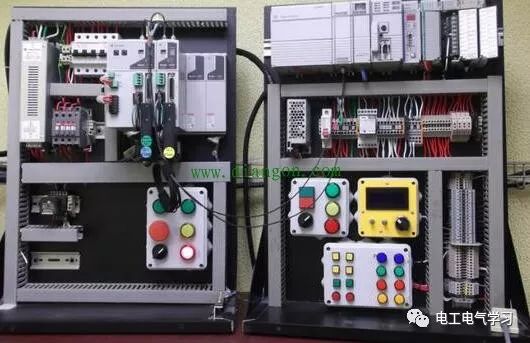
Our steel poles are made from quality sheet through bending, forming, automatic welding and hot galvanization
We can reach one-run machining length of 14m and can bend sheet of thickness up to 45mm
We adopt advanced welding procedures, automatically weld main joints and reach rank-II welding quality.
7 steps to debug the designed electrical system
It is located in the beach of scenic and rich Taihu Yixing with good transport service.
The company is well equipped with advanced manufacturing facilities.
We own a large-sized numerical control hydraulic pressure folding machine with once folding length 16,000mm and the thickness 2-25mm.
We also equipped with a series of numerical control conveyor systems of flattening, cutting, folding and auto-welding, we could manufacture all kinds of steel poles and steel towers.
Our main products: high & medium mast lighting, road lighting, power poles, sight lamps, courtyard lamps, lawn lamps, traffic signal poles, monitor poles, microwave communication poles, etc. Our manufacturing process has been ISO9001 certified and we were honored with the title of the AAA grade certificate of goodwill.
Presently 95% of our products are far exported to Europe, America, Middle East, and Southeast Asia, and have enjoyed great reputation from our customers.
So we know the demand of different countries and different customers.
We are greatly honored to invite you to visit our factory and cheerfully look forward to cooperating with you.